Arduinoではディスプレイに数字を自由に表示するのが難しい。
そこで小数点表示することを色々と調べた。
Sketch
// include the library code:
#include <LiquidCrystal.h>
// refer to http://garretlab.web.fc2.com/arduino/reverse_lookup/index.html
// initialize the library with the numbers of the interface pins
//LiquidCrystal(rs, enable, d4, d5, d6, d7)
LiquidCrystal lcd(12, 11, 7, 6, 5, 4);
void setup() {
// set up the LCD's number of columns and rows:
lcd.begin(16, 2);
// Print a message to the LCD.
lcd.home();
Serial.begin(9600);
char s[16];
char t[16];
//double val = 12.345678;
double val = -12.345678;
dtostrf(val, 5, 1, s);
Serial.println(s);
lcd.print(s);
val = -12.345678;
dtostrf(val, 5, 2, s);
lcd.setCursor(8,0);
lcd.print(s);
if( val>0) {
Serial.print("+");
Serial.println(s);
}
else{
Serial.println(s);
}
sprintf(t, "Val = %s", dtostrf(val, 5, 10, s));
Serial.println(t);
lcd.setCursor(0,1);
lcd.print(t);
dtostre(val, s, 3, DTOSTR_ALWAYS_SIGN|DTOSTR_PLUS_SIGN);
Serial.println(s);
}
void loop() {
}
/*
LiquidCrystal Library - display() and noDisplay()
Demonstrates the use a 16x2 LCD display. The LiquidCrystal
library works with all LCD displays that are compatible with the
Hitachi HD44780 driver. There are many of them out there, and you
can usually tell them by the 16-pin interface.
This sketch prints "Hello World!" to the LCD and uses the
display() and noDisplay() functions to turn on and off
the display.
The circuit:
* LCD RS pin(pin 4) to digital pin 12
* LCD Enable pin(pin 6) to digital pin 11
* LCD D4 pin(pin 11)to digital pin 7
* LCD D5 pin(pin 12) to digital pin 6
* LCD D6 pin(pin 13) to digital pin 5
* LCD D7 pin(pin 14) to digital pin 4
* LCD R/W pin(pin 5) to ground
* 10K resistor:
* ends to +5V and ground
* wiper to LCD VO pin (pin 3)
Library originally added 18 Apr 2008
by David A. Mellis
library modified 5 Jul 2009
by Limor Fried (http://www.ladyada.net)
example added 9 Jul 2009
by Tom Igoe
modified 22 Nov 2010
by Tom Igoe
This example code is in the public domain.
http://www.arduino.cc/en/Tutorial/LiquidCrystal
*/
2012年5月1日火曜日

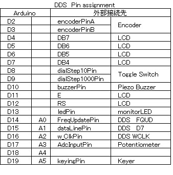
2012年4月20日金曜日
モールス信号練習機
bounceをsketchして、押しボタン(電鍵の代わり)を押すとブザーが鳴り、同時にLEDが光る。
モールス信号の練習機をブレッドボード上で作成する。
Sketch
/* bounce
内部プルアップ抵抗20 kohmを有効にする
The circuit:
LED attached from pin 13 to ground
This code turns a led on/off through a debounced button(keyingPin)
*/
#include <Bounce.h>
int buzzerPin=10;
int ledPin=13;
int keyingPin=19;
// Instantiate a Bounce object with a 5 millisecond debounce time
Bounce bouncer = Bounce( keyingPin,5 );
void setup() {
pinMode(buzzerPin, OUTPUT); // sets the pin as output
pinMode(keyingPin,INPUT); // sets the pin as input
pinMode(ledPin,OUTPUT); // sets the pin as output
digitalWrite(keyingPin,HIGH);
}
void loop() {
bouncer.update ( ); // Update the debouncer
int value = bouncer.read(); // Get the update value
if ( value == LOW) { // Turn on or off the LED
digitalWrite(ledPin, HIGH );
analogWrite(buzzerPin,128);
} else {
digitalWrite(ledPin, LOW );
analogWrite(buzzerPin, 0);
}
}
モールス信号の練習機をブレッドボード上で作成する。
Sketch
/* bounce
内部プルアップ抵抗20 kohmを有効にする
The circuit:
LED attached from pin 13 to ground
This code turns a led on/off through a debounced button(keyingPin)
*/
#include <Bounce.h>
int buzzerPin=10;
int ledPin=13;
int keyingPin=19;
// Instantiate a Bounce object with a 5 millisecond debounce time
Bounce bouncer = Bounce( keyingPin,5 );
void setup() {
pinMode(buzzerPin, OUTPUT); // sets the pin as output
pinMode(keyingPin,INPUT); // sets the pin as input
pinMode(ledPin,OUTPUT); // sets the pin as output
digitalWrite(keyingPin,HIGH);
}
void loop() {
bouncer.update ( ); // Update the debouncer
int value = bouncer.read(); // Get the update value
if ( value == LOW) { // Turn on or off the LED
digitalWrite(ledPin, HIGH );
analogWrite(buzzerPin,128);
} else {
digitalWrite(ledPin, LOW );
analogWrite(buzzerPin, 0);
}
}
ディスプレイの設定
ディスプレイには秋月電子のものを使用した。
ディスプレイ Arduino
LCD-DB7 14pin D4
LCD-DB6 13pin D5
LCD-DB5 12pin D6
LCD-DB4 11pin D7
LCD-E 6pin D11
LCD-R/W 5pin
LCD-RS 4pin D12
LCD-Vo 3pin potentiometerの中点で端点はGNDと+5v
2pin +5V
1pin GND
16pin GND
15pin +4.2V 抵抗100 ohmを経由する
Sketch
// include the library code:
#include <LiquidCrystal.h>
// initialize the library with the numbers of the interface pins
//LiquidCrystal(rs, enable, d4, d5, d6, d7)
LiquidCrystal lcd(12, 11, 7, 6, 5, 4);
void setup() {
// set up the LCD's number of columns and rows:
lcd.begin(16, 2);
// Print a message to the LCD.
lcd.home();
lcd.print("Hello, World!");
lcd.setCursor(0,1);
lcd.print("JA1NHL");
lcd.setCursor(10,1);
}
void loop() {
// Turn off the display:
lcd.noDisplay();
delay(500);
// Turn on the display:
lcd.display();
delay(500);
}
/*
LiquidCrystal Library - display() and noDisplay()
Demonstrates the use a 16x2 LCD display. The LiquidCrystal
library works with all LCD displays that are compatible with the
Hitachi HD44780 driver. There are many of them out there, and you
can usually tell them by the 16-pin interface.
This sketch prints "Hello World!" to the LCD and uses the
display() and noDisplay() functions to turn on and off
the display.
The circuit:
* LCD RS pin(pin 4) to digital pin 12
* LCD Enable pin(pin 6) to digital pin 11
* LCD DB4 pin(pin 11)to digital pin 7
* LCD DB5 pin(pin 12) to digital pin 6
* LCD DB6 pin(pin 13) to digital pin 5
* LCD DB7 pin(pin 14) to digital pin 4
* LCD R/W pin(pin 5) to ground
* 10K resistor:
* ends to +5V and ground
* wiper to LCD VO pin (pin 3)
Library originally added 18 Apr 2008
by David A. Mellis
library modified 5 Jul 2009
by Limor Fried (http://www.ladyada.net)
example added 9 Jul 2009
by Tom Igoe
modified 22 Nov 2010
by Tom Igoe
This example code is in the public domain.
http://www.arduino.cc/en/Tutorial/LiquidCrystal
*/
完成すると Hello, World!
JA1NHL
と表示され、表示が点滅する。
ディスプレイ Arduino
LCD-DB7 14pin D4
LCD-DB6 13pin D5
LCD-DB5 12pin D6
LCD-DB4 11pin D7
LCD-E 6pin D11
LCD-R/W 5pin
LCD-RS 4pin D12
LCD-Vo 3pin potentiometerの中点で端点はGNDと+5v
2pin +5V
1pin GND
16pin GND
15pin +4.2V 抵抗100 ohmを経由する
Sketch
// include the library code:
#include <LiquidCrystal.h>
// initialize the library with the numbers of the interface pins
//LiquidCrystal(rs, enable, d4, d5, d6, d7)
LiquidCrystal lcd(12, 11, 7, 6, 5, 4);
void setup() {
// set up the LCD's number of columns and rows:
lcd.begin(16, 2);
// Print a message to the LCD.
lcd.home();
lcd.print("Hello, World!");
lcd.setCursor(0,1);
lcd.print("JA1NHL");
lcd.setCursor(10,1);
}
void loop() {
// Turn off the display:
lcd.noDisplay();
delay(500);
// Turn on the display:
lcd.display();
delay(500);
}
/*
LiquidCrystal Library - display() and noDisplay()
Demonstrates the use a 16x2 LCD display. The LiquidCrystal
library works with all LCD displays that are compatible with the
Hitachi HD44780 driver. There are many of them out there, and you
can usually tell them by the 16-pin interface.
This sketch prints "Hello World!" to the LCD and uses the
display() and noDisplay() functions to turn on and off
the display.
The circuit:
* LCD RS pin(pin 4) to digital pin 12
* LCD Enable pin(pin 6) to digital pin 11
* LCD DB4 pin(pin 11)to digital pin 7
* LCD DB5 pin(pin 12) to digital pin 6
* LCD DB6 pin(pin 13) to digital pin 5
* LCD DB7 pin(pin 14) to digital pin 4
* LCD R/W pin(pin 5) to ground
* 10K resistor:
* ends to +5V and ground
* wiper to LCD VO pin (pin 3)
Library originally added 18 Apr 2008
by David A. Mellis
library modified 5 Jul 2009
by Limor Fried (http://www.ladyada.net)
example added 9 Jul 2009
by Tom Igoe
modified 22 Nov 2010
by Tom Igoe
This example code is in the public domain.
http://www.arduino.cc/en/Tutorial/LiquidCrystal
*/
完成すると Hello, World!
JA1NHL
と表示され、表示が点滅する。
2012年3月16日金曜日
Buzzerを鳴らす
Sketch
/*
Buzzer
Drive a piezoelectric buzzer with Arduino
http://tronixstuff.wordpress.com/tutorials > Chapter 13
*/
int ledPin=13; //monitor
int buzzerPin=10; //ブザーを接続
void setup()
{
pinMode(ledPin, OUTPUT); // sets the pin as output
pinMode(buzzerPin, OUTPUT); // sets the pin as output
}
void loop()
{
digitalWrite(ledPin, HIGH);
analogWrite(buzzerPin,128); //音量 半分
delay(500);
digitalWrite(ledPin, LOW);
analogWrite(buzzerPin, 0); //消音
delay(500);
}
/*
Buzzer
Drive a piezoelectric buzzer with Arduino
http://tronixstuff.wordpress.com/tutorials > Chapter 13
*/
int ledPin=13; //monitor
int buzzerPin=10; //ブザーを接続
void setup()
{
pinMode(ledPin, OUTPUT); // sets the pin as output
pinMode(buzzerPin, OUTPUT); // sets the pin as output
}
void loop()
{
digitalWrite(ledPin, HIGH);
analogWrite(buzzerPin,128); //音量 半分
delay(500);
digitalWrite(ledPin, LOW);
analogWrite(buzzerPin, 0); //消音
delay(500);
}
2012年1月3日火曜日
押しボタンを押した回数をカウントする
Sketch
/*
pushbuttonをおした回数をカウントする
counter
The circuit:
* +5Vと2番ピンの間にpushbuttonを接続する
* 抵抗10Kを2番ピンとグランドの間に接続する
*
This example code is in the public domain.
http://arduino.cc/en/Tutorial/ButtonStateChange
4回ごとにLEDが点灯する
*/
int buttonPin = 2; // 押しボタン
int ledPin = 13; // 内蔵LED
int buttonPushCounter = 0; // カウンター
int buttonState = 0; // 押しボタンの状態
int lastButtonState = 0; // 前回の押しボタンの状態
void setup() {
// 入力に設定
pinMode(buttonPin, INPUT);
// LEDを出力に設定
pinMode(ledPin, OUTPUT);
// シリアルを設定
Serial.begin(9600);
}
void loop() {
// 押しボタンを読取
buttonState = digitalRead(buttonPin);
// 前回の状態と比較
if (buttonState != lastButtonState) {
//状態が変化していたらカウンター数を加数
if (buttonState == HIGH) {
// 現在の状態がHIGHならif the current state is HIGH then the button
// wend from off to on:
buttonPushCounter++;
Serial.println("on");
Serial.print("number of button pushes: ");
Serial.println(buttonPushCounter);
}
else {
// 現在の状態がLOWならif the current state is LOW then the button
// wend from on to off:
Serial.println("off");
}
}
// 次回のために現在の状態を最後の状態と差し替えるsave the current state as the last state,
//for next time through the loop
lastButtonState = buttonState;
// 4回ごとにLEDを点灯させるtturns on the LED every four button pushes by
// checking the modulo of the button push counter.
// the modulo function gives you the remainder of
// the division of two numbers:
if (buttonPushCounter % 4 == 0) {
digitalWrite(ledPin, HIGH);
} else {
digitalWrite(ledPin, LOW);
}
}
/*
pushbuttonをおした回数をカウントする
counter
The circuit:
* +5Vと2番ピンの間にpushbuttonを接続する
* 抵抗10Kを2番ピンとグランドの間に接続する
*
This example code is in the public domain.
http://arduino.cc/en/Tutorial/ButtonStateChange
4回ごとにLEDが点灯する
*/
int buttonPin = 2; // 押しボタン
int ledPin = 13; // 内蔵LED
int buttonPushCounter = 0; // カウンター
int buttonState = 0; // 押しボタンの状態
int lastButtonState = 0; // 前回の押しボタンの状態
void setup() {
// 入力に設定
pinMode(buttonPin, INPUT);
// LEDを出力に設定
pinMode(ledPin, OUTPUT);
// シリアルを設定
Serial.begin(9600);
}
void loop() {
// 押しボタンを読取
buttonState = digitalRead(buttonPin);
// 前回の状態と比較
if (buttonState != lastButtonState) {
//状態が変化していたらカウンター数を加数
if (buttonState == HIGH) {
// 現在の状態がHIGHならif the current state is HIGH then the button
// wend from off to on:
buttonPushCounter++;
Serial.println("on");
Serial.print("number of button pushes: ");
Serial.println(buttonPushCounter);
}
else {
// 現在の状態がLOWならif the current state is LOW then the button
// wend from on to off:
Serial.println("off");
}
}
// 次回のために現在の状態を最後の状態と差し替えるsave the current state as the last state,
//for next time through the loop
lastButtonState = buttonState;
// 4回ごとにLEDを点灯させるtturns on the LED every four button pushes by
// checking the modulo of the button push counter.
// the modulo function gives you the remainder of
// the division of two numbers:
if (buttonPushCounter % 4 == 0) {
digitalWrite(ledPin, HIGH);
} else {
digitalWrite(ledPin, LOW);
}
}
2012年1月1日日曜日
割り込みの状態が変化したらLEDを反転させる
Sketch
//デジタルピン2(割り込みピン)の状態が変化したらLEDを反転させる
int ledPin=13;
volatile int state = LOW;
void setup() {
pinMode(ledPin,OUTPUT);
//attachInterrupt(0, blink, CHANGE); //0->デジタルピン2 1->デジタルピン3
attachInterrupt(0, blink, RISING); //デジタルピン2 LOW-->HIGH
//attachInterrupt(0, blink, FALLING); //デジタルピン2
}
void loop() {
digitalWrite(ledPin,state);
}
void blink() {
state= !state;
}
//デジタルピン2(割り込みピン)の状態が変化したらLEDを反転させる
int ledPin=13;
volatile int state = LOW;
void setup() {
pinMode(ledPin,OUTPUT);
//attachInterrupt(0, blink, CHANGE); //0->デジタルピン2 1->デジタルピン3
attachInterrupt(0, blink, RISING); //デジタルピン2 LOW-->HIGH
//attachInterrupt(0, blink, FALLING); //デジタルピン2
}
void loop() {
digitalWrite(ledPin,state);
}
void blink() {
state= !state;
}
登録:
投稿 (Atom)